There are many clutch style NC machines such as G&L or Fraser still out there. Many are barely running or are not running at all due to control related issues. Most of these machines are very solid and rigid machines that could still have many more years of service life. MasterControls has experience giving new life to these types of machines.
There are typically 2 options a customer can take when updating these type of machines.
1. Keep the NC functionality for positioning (such as drilling) and point to point moves
2. Update the machine to full CNC capability (circular interpolation possible)
Option#1: NC functionality (Non-interpolated)
Step 1:
In order to update an existing clutch style machine point to point position you must first have a control that is capable of executing special G-codes or low level CNC operations to position the axes using the machines clutch system. MCI has used NUM and/or Power Automation (formally MachineMate) controls for such tasks. Much of the actual NC control is done in the PLC.
Step 2:
The machine feedback must be suitable for the control used. MCI will either convert feedback signals such as Inductosyn/resolver or replace the feedback with Newall scales (especially linear axes). Ultimately, the feedback sign to these type of controls needs to be encoder type (AqBq- differential line driver/TTL).
Step 3:
The machine’s existing clutch systems and clutch hydraulics need to be fully functional. In cases where this is not possible and/or there is a reliability issue with the clutch system, MCI can replace the main motor with a servo to do the positioning in one clutch range. In this case, the machine clutches for selecting the different axes still need to be operational. The customer may need to drive the hydraulic system with a separate pump as some times these systems use the same motor for main drive and hydraulic pump.
Step 4:
Many times on these machines the Z axis or quill is driven by the spindle motor. It will need to be determined if this is kept “as is” or uncoupled for servo control.
NC Example:
On the machine shown below (G&L Fraser) the following was done for the conversion:
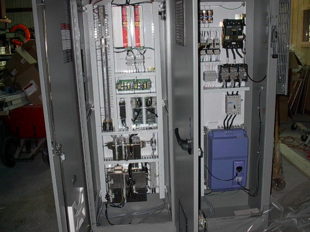
• New electrical enclosure
• New scales on X, Y, and W axes- these axes positioned as NC point to point
• Spindle drive and motor added to drive spindle (for rigid tapping)
• Z axis servo added for quill movement (for rigid tapping)
• B axis servo added to position rotary table
• Resolver converters used on spindle and B axis
Option#2: Full CNC capability
Step 1:
In order to update these type of machines to full CNC capability it is recommend that they have ballscrews or the existing Acme style screws be replaced with ballscrews. If this is not done, the machine will only be able to do positioning moves and no circular interpolation.
Step2:
Based on the customer’s requirements a determination will be made if scales are needed due to accuracy. In most cases this is not needed and the positioning device is the motor itself (position read off motor feedback).
Step3:
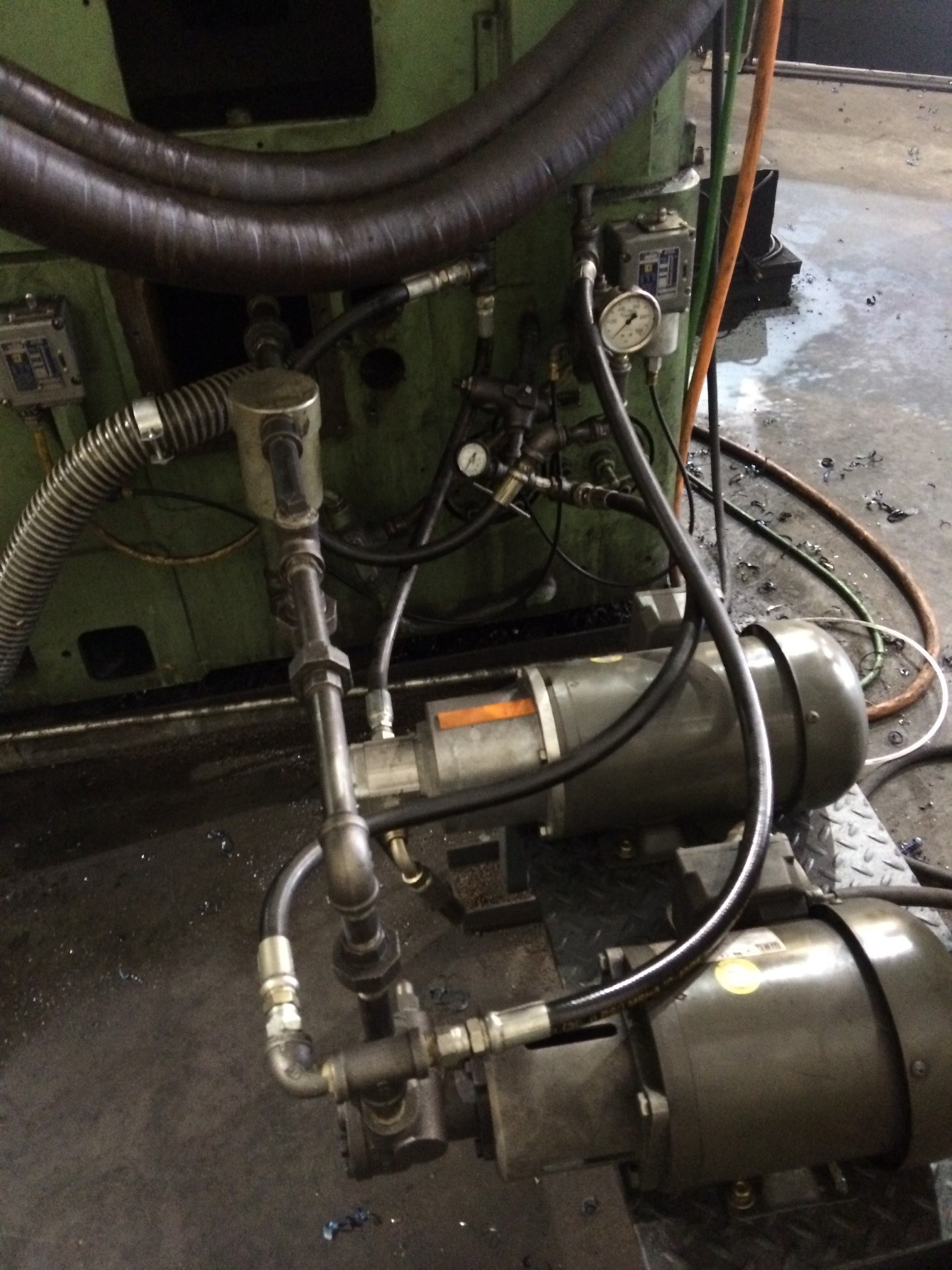
The customer may need to drive the hydraulic system with a separate pump as some times these systems use the same motor for main drive and hydraulic pump. Typically in these cases the clutch system and the main drive motor are removed from the bottom of the machine and the W and X axes are located in old hydraulic location.
Step4:
Many times on these machines the Z axis or quill is driven by the spindle motor. It will need to be decided if this is kept “as is” or uncoupled for servo control.
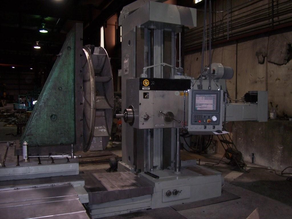
CNC Example:
In the machine shown below (G&L) the following was done for the conversion
• New electrical enclosure
• New absolute digital drive system for 3 axes
• Hydraulic system replaced
• Clutch system and old hydraulics removed from bottom of machine.
• X & W servos located in old hydraulic location
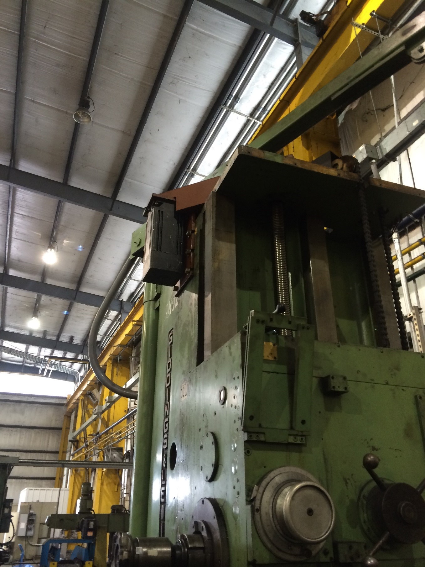
• Y axis servo located on top of machine
• New operator pendant arm and station
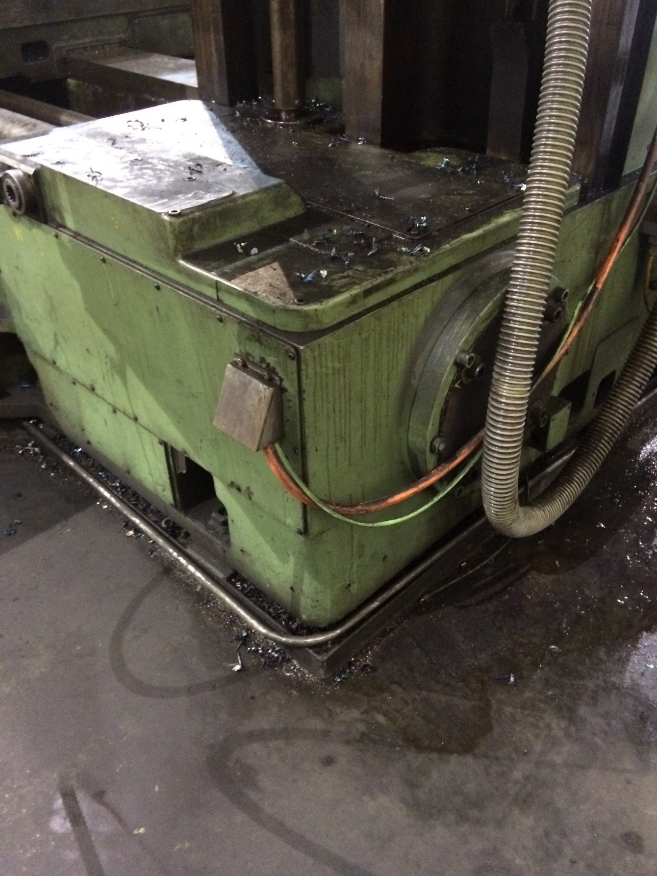
New y-axis servo motor shown
Replacement of main drive motor
Replacement of hydraulic system